Here you can find information on recent research activites and findings
Barrier island evolution
in Ria Formosa (S. Portugal) over multidecadal scales
Barrier island resilience
using ecological resilience theory concepts and principles
Modelling coastal evolution
coupling beach-dune morphodynamics over distinct temporal scales
Long-term response of Ria Formosa barrier islands – impacts of human actions
The morphological evolution analysis was based on aerial photographs that cover the period from 1952 to 2014. Distinct geomorphological units were digitised and analysed, using four boundaries:
- a) The ocean-side coastline (ca. Mean High Water Level: MHWL). The proxies used were the upper debris line or the beach scarp, in cases of debris absence.
- b) The dune line (ca. Mean Higher High Water Level: MHHWL), using the ocean-side limit of dune vegetation, as proxy for the position of the foredune foot.
- c) The backbarrier coastline in the lagoon-side (ca. MHWL). It corresponds to the limit between the upper-marsh vegetation and the barrier/dune (in perched marshes), or to the debris line or beach scarp/dune limit (in backbarrier beaches).
- d) The marsh-edge line (transition from marsh to tidal flat; ca. MWL).
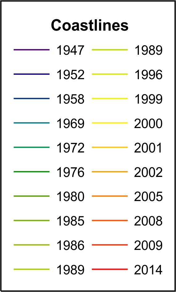
The mapped boundaries corresponding to MHWL in the ocean and the backbarrier are shown in the interactive map below (the legend is shown on the left).
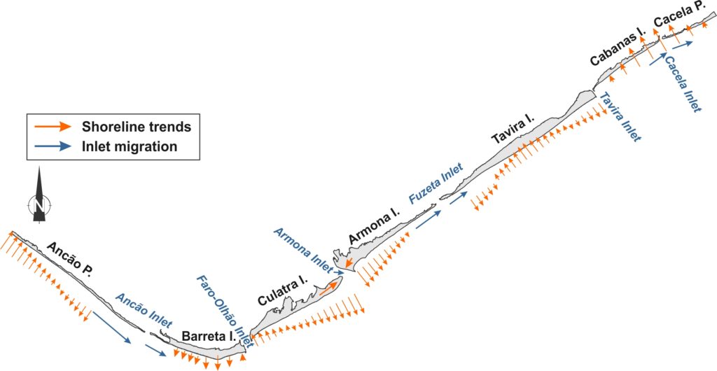
Barrier area in the Ria Formosa system grew by 2.5·106 m2 (17%) during the study period, with a linear trend of 4.3·105 m2/yr (R2=0.95, p<0.01) up to 2005 and negligible rates thereafter, which could indicate that the system is reaching morphodynamic stability. Therefore, the barrier system was effective in trapping and incorporating sediment, with the principal mechanisms of barrier growth related to attachment of shoals and Longshore Sediment Transport (LST). Shoal attachment has been shown to be the main mechanism responsible for morphological change in Culatra and west Armona islands, through the remobilization and landward transport of ebb delta sediments by waves and flood tidal currents, after the ebb tidal current loss in Armona Inlet. The dominance of LST in the remaining barriers is substantiated by the prevailing eastward inlet migration. Potential secondary contributions, such as interannual variability in cross-shore sediment exchange, cannot be separated from the primary ones in the analysis performed. It is noted that the landward migration of C-C (up to 1986) was also assisted by the presence of flood delta and/or inlet related deposits that allowed the growth of Cabanas Island. Assuming that the growth of Culatra and Armona W is exclusively due to shoal attachment and that the rest of the barriers grew only due to LST, it follows that shoal incorporation was the main mechanism promoting growth in Ria Formosa (70% ±5.8%). Shoal attachment takes place almost equally between Culatra and Armona W (60% and 40% ±2.3%, respectively). The incorporation of these shoals promoted a wide morphology in Armona W, very different to the elongated spit formations in east Culatra. Barreta dominates the growth due to LST in system, while the relative contribution of Ancão decreases with time. LST incorporation in Ancão relative to 1952 is steadily negative after 2001, which, combined with the erosion in west Ancão, indicates that the Vilamoura jetties have significantly limited barrier growth. Growth in C-C regained pre-intervention values after 2002, with full barrier recovery circa 40 years after the first signs of coastal retreat. The major shoreline evolution trends of Ria Formosa between 1952 and 2014 are summarised in the figure below.
The table includes a synopsis of the main evolution regimes and the related controlling factors promoting or inhibiting growth or stability (artificial or natural). Soft interventions, such as beach and dune nourishments generally promote growth, while inlet relocations inhibit natural inlet breaching/closure and start a new migration cycle.
![Table. Morphological barrier evolution regimes regarding coverage (LSG: Long-Shore Growth; CSG: Cross-Shore Growth; CSN: Cross-Shore Narrowing), backbarrier and marsh and related main artificial (V.: Vilamoura; F-O: Faro-Olhão; NR: Nourishment; IR: Inlet Relocations) and natural drivers of change (LST: Longshore Sediment Transport; SBL: Shallow Backbarrier Lagoon). Factors inhibiting and promoting barrier growth and/or stability are denoted with [-] and [+], respectively.](http://kobiadou.webpages.auth.gr/wordpress/wp-content/uploads/2020/03/table_RF_evolution_factors-1024x621.png)
The analysis showed that the hard engineering works, implemented within the system and in the updrift zone, had a decisive influence on barrier evolution. Overall, the barrier system was effective in trapping and incorporating sediment, reaching an increase of 17% in barrier coverage during the timeframe of analysis. The main sediment source promoting growth was the incorporation of shoals (70%) and, to a lesser extent, longshore drift (30%).
Based on the results, four evolution regimes were identified:
- Artificially enhanced growth: identified in the updrift and the downdrift zone of stabilised inlets (the latter due to tidal prism loss in the non-migrating, downdrift inlet, combined with ebb shoal presence).
- Stability promoted by natural or natural and artificial factors: identified in barriers with broad backbarrier platforms.
- Artificially triggered decay that can lead to inland migration: identified in barriers subjected to longshore drift reduction (e.g. updrift shore-perpendicular structure); rollover is supported by natural mechanisms (overwash, shallow backbarrier lagoon).
- Natural growth: identified during barrier recuperation, following (artificially triggered) barrier rollover.
Comparison with other barrier systems showed similarities and differences in barrier response to artificial triggers. Similarities (accretion updrift and erosion downdrift) were identified in response to longshore drift changes and differences (barrier gains at Ria Formosa, versus losses in other systems) in response to inlet tidal prism reduction. At Ria Formosa, shoal attachment was initiated by the loss of hydraulic efficiency in a non-migrating, natural, inlet, characteristic that was crucial for the incorporation of shoals to the advantage of the barriers (and not at their expense, as evidenced in cases of migrating inlets). With this work, we hope to inspire detailed and quantified studies of human interventions on coastal evolution and to improve coastal management actions, based on observed impacts and changes at decadal to century scales.
Related research project: EVREST: Evolution and Resilience of Barrier Island Systems
Related papers:
- Kombiadou, K., Matias, A., Ferreira, Ó., Carrasco, A.R., Costas, S., Plomaritis, T. (2019). Impacts of human interventions on the evolution of the Ria Formosa barrier island system (S. Portugal). Geomorphology, 343, 129-144. link
- Kombiadou, K., Matias, A., Carrasco, R., Ferreira, Ó., Costas, S. and Vieira, G. (2018). Towards Assessing the Resilience of Complex Coastal Systems: Examples from Ria Formosa (South Portugal). Journal of Coastal Research, Special Issue No. 85, pp. 646–650 link
Dataset:
Kombiadou, Katerina; Matias, Ana; Costas, Susana; Carrasco, A. Rita; Plomaritis, Theocharis; Ferreira, Óscar (2020), “Ria Formosa barrier island shorelines and long-term cross-shore rates between 1952 and 2014”, Mendeley Data, V1, https://doi.org/10.17632/96sfy77s3z.1
EVREST team membes that participated in the work
Assessing barrier island resilience using the ecological resilience principles
Resilience, highly important in the context of achieving sustainability, is a multi-faceted concept that has been adapted differently to various uses and contexts. These multiple uses of the term, with different objectives, over a broad contextual frame and with a mixture of descriptive and normative aspects has led to divergent conceptions of resilience, ambiguous uses of terminology and to an increasingly diluted and unclear specific meaning of resilience. Distinct views, perceptions and definitions seem to coexist even within disciplines (e.g., physics, ecology, geography, psychology, economy), while, between disciplines, the differences are even more significant. The term has been used ambiguously and for fundamentally different intentions, giving rise to trade-offs between social and environmental objectives, while resilience is increasingly conceived as a perspective, rather than a clear and well-defined concept. At the same time, increasing interest, is noted within the research community regarding ecological (or ecosystem) resilience (or resiliency), concept gaining ground over more rigid views of natural systems, like the engineering resilience.
Ecological resilience is currently defined as ‘the capacity of a system to absorb disturbance and re-organize while undergoing change so as to still retain essentially the same functions, structure, identity and feedbacks’.
(Flood and Schechtman, 2014; Folke, 2006; Scheffer and Carpenter, 2003; Walker et al., 2004).
There are four crucial aspects of resilience (the first three can apply both to a whole system and to the sub-systems that make it up):
- Latitude: the maximum amount a system can be changed before losing its ability to recover within the same state (before crossing a threshold), equal to the width of the basin of attraction.
- Resistance: the ease or difficulty of changing the system; deep basins of attraction indicate that greater disturbances are required to change the current state of the system.
- Precariousness: how close the current state of the system is to a limit or “threshold” that, if breached, makes reorganization difficult or impossible.
- Cross-scale interactions (i.e. Panarchy): the resilience of a system at a particular focal scale will depend on the influences from states and dynamics at scales above and below. They express how the other three attributes are influenced by the states and dynamics of the (sub)systems at scales above and below the scale of interest.
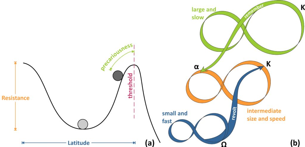
The first three ‘dimensions’ of resilience are related to the shape of the basin of attraction and the system state (ball), as graphically depicted in the fugure below (in a). It is important to keep in mind that the representation of a system using the ball-and-cup analogy is referring to a specific set of conditions (in time and space) and that these dimensions are not to be perceived as static. The shape of the stability domain (cup) and of the entire stability landscape are continuously changing in response to the combined effects of natural processes and interactions and external disturbances, as well as the system state itself.
Cross-scale connections refer to the way complex adaptive system components interact with one another, not within a hierarchy (only top-down interactions), but within a panarchy (named after the bi-faceted, good-bad, Greek god Pan), a theory put forward by Gunderson and Holling. Based on this theory, two cross-scale (panarchical) connections that become important at times of change and renewal in the adaptive cycle are the most significant ones. They are termed “Revolt” and “Remember” (Fig. b) and are different in terms of direction within the panarchy (from higher to lower cycles and vice versa) and of the nature (destructive or creative) of the feedback. The former refers to a collapsing lower, faster cycle, whose impacts may cascade up to the next larger and slower level, potentially triggering a crisis, especially if the upper level is at the K phase. The latter refers to the organisation of opportunities and constraints for the renewal of a, previously collapsed, lower cycle, by the K phase of a slower and larger level. Thus, a revolt connection suggests conditions where fast and small events overwhelm slow and large ones, whereas a remember connection facilitates renewal, by drawing upon the potential accumulated and stored in a larger, slower cycle.
Ecological resilience is a measure of regional topography of the stability landscape (Gunderson et al., 2009), with thresholds that act as tipping points between BoAs existing at multiple scales (Thoms et al., 2018a). Identifying where thresholds might lie and understanding them is paramount in ecological resilience thinking (Walker and Salt, 2006). It follows that defining the potential stable states is a crucial first step in assessing the ecological resilience of a natural system. For barrier islands, the most basic division for the structure of the subaerial part of the barrier is into wave-, wind- and tide-dominated morphological units. These three units, simply termed Beach, Dune and Marsh (BDM), can be used to express all potential stable states of barrier islands. These combinations are given in the Fig. below, using a binary naming system to distinguish the presence (1) or absence (0) of each unit within the BDM state sequence (e.g. 010: only D is present; 110: B and D are present, etc.). Each BDM state represents a distinct BoA, where the system is characterised by a different set of processes, functions and feedbacks, inextricably linked to the BDM structure, itself. A change in a BDM barrier state implies a (temporary or permanent) threshold crossing to a new BoA, characterised by the new BDM structure. However, not all thresholds lead to regime shifts (Parsons et al., 2009). The natural maturation process of a barrier, like the development of a new environment (e.g., a shift from a 110 to 111 BDM state), cannot be related to loss of resilience and, therefore, only threshold crossing under destructive processes (right to left transition in Fig.) should be considered as such.

To pass from geomorphological dimensions to resilience, the first step is the assessment of the system state and the identification of thresholds and changes to the stability landscape. The temporal changes in BDM states, latitude and precariousness along the TRs of C-C, are given in the Fig. (a, b and c, respectively). Thresholds are identified throughout the domain and are classified in terms of severity in 3 classes (loss of B, D or M), considering the loss of the unit of highest complexity. For example, a transition of 111 to 000 (e.g. over TR 7-8 between 1958 and 1972), denoting the loss of all units, has been characterised a level 3 threshold (M loss), from the loss of the upper cycle of the BDM panarchy. This distinction aims at providing an indication of the permanence of the shift, as the higher the unit level in the panarchy, the slower its recovery is expected to be. At the same time, threshold type can indicate the potential disturbance causing the perturbation, as for example the loss of B, D and M can be associated with collision, overwash and inundation regimes of the Sallenger storm impact scale (Sallenger, 2000) (see also Kombiadou et al. (2019a)). As indicated previously, human activities (i.e. management practices) can be a major factor that needs to be taken into consideration when interpreting shifts, as their influence (positive or negative feedback) is exerted simultaneously with other forcing factors, and may not be directly reflected by the threshold type. Known human interventions were taken into account during analysis and interpretation of the results.
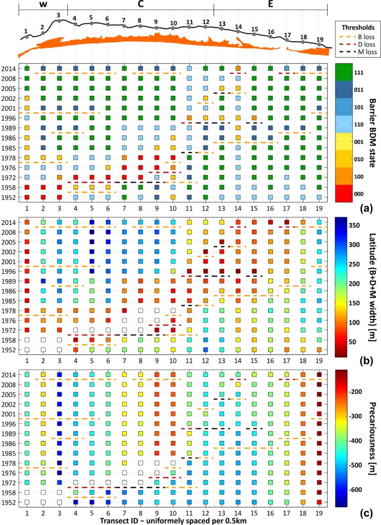
A number of significant shifts can be identified in space and time in C-C (Fig.). Overall, the most prominent and extensive BDM state change was the shift to state 000 over a zone of 2.5 km between 1958 and 1972 (TR 4-8 in Fig.). This shift is related to the human-induced (stabilisation of Tavira Inlet with jetties, directly updrift) reduction of longshore drift that initiated erosion and landward migration in the area that lasted until 1986 (Kombiadou et al., 2019b). The change in barrier state is associated with D or M loss threshold. Taking into account that the actual shift of the barrier stretch to state 000 took place around the mid to late 1960s (Kombiadou et al., 2019a), it follows that the permanence of the regime shift ranged between 10 and 20 years. Regeneration of B, D and M units over this zone was of the order of 2-4, 4-7 and 10-20 years, respectively. The recovery over the stretch took place from west to east and was related with a period of latitude readjustment, with faster widening of the BoAs during the first stages of barrier reestablishment (regeneration of B and D) and slower after M development. As expected, the precariousness over this stretch increased rapidly (by 4-7.5 m/yr) during the rollover phase (until 1986), while the total increase in precariousness during the study period ranged within 20-35 %. Eastwards (TR 11 to 15), the shifts associated with high-level thresholds (M and D loss), noted at a later stage (1989-1996), are related with an inlet breaching event (near TR 15) that was subsequently artificially closed (1997).
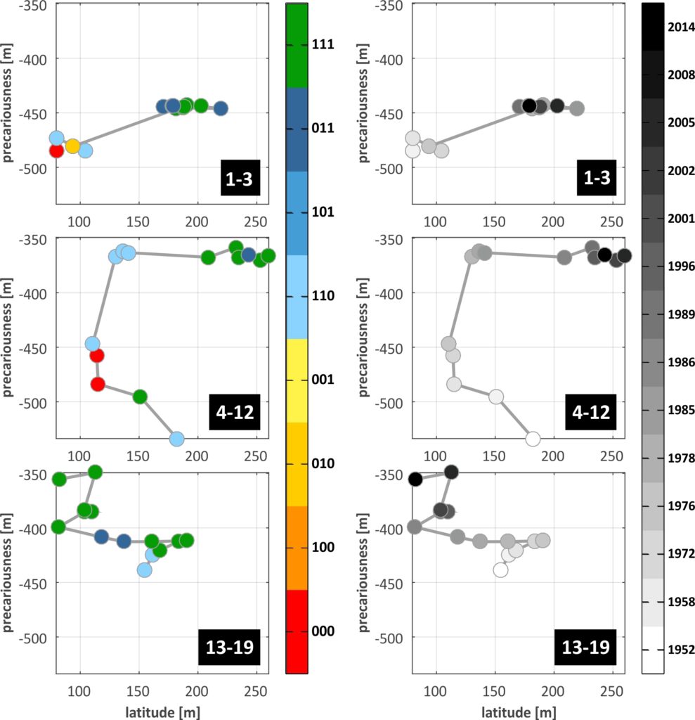
From the scale of the individual transects we pass on to barrier sectors through averaging of resilience dimensions over TR groups and identification of the dominant BDM state. The grouping of transects of C-C is shown in the Fig. below, in the form of resilience trajectories, where the temporal evolution of the available resilience dimensions (latitude and precariousness) are plotted against each other (the plots are given twice , with the colour of the trajectory points denoting the BDM state in one (left) and time in the other (right)). The most abundant BDM state in the TRs that comprise each sector was selected as the dominant BDM state that should characterise the entire sector. The effectiveness of this selection and its impact on threshold identification can be examined comparing individual thresholds with grouped ones.The West sector of C-C (TR 1-3, top in Fig.) shows a distinct ‘jump’ in the trajectory between 1978 and 1985, with strong widening of the BoA and increase in precariousness. Thereafter dimensions remain mostly stabilised, while four B loss thresholds are identified in the entire period (1976-78, 1986-89, 1996-2001 and 2008-14).
In the Central sector (TR 4-12, middle in Fig.), the trajectory shows a contraction of the BoA during the first 30 years, with a severe threshold related to total depletion of the barrier (from 111 to 000), taking place between 1958 and 1972. The 000 state persisted until 1978, when BDM state switched to 110, with low latitude values and gradually increasing precariousness until 1985, when inland migration ceased. From then on, the Central sector shows mostly stabilised precariousness, strong widening of the BoA and transition to more mature and complex barrier structure (M development), with a B loss threshold noted between 2008 and 2014. Regarding the East sector (TR 13-19, bottom in Fig.), the trajectory shows an initial phase of maturation and widening of the BoA that lasted until 1978, after which strong narrowing (by around 6 m/yr) prevailed until 1996. During this phase, a B loss threshold was crossed (1985-86) and the 111 barrier state was restored (1996). Afterwards, the sector showed a rise and fall in latitude and more rapid increase in precariousness.
In general, resilience trajectories are an effective way of visualising the evolution of all resilience criteria and dimensions in a single plot, allowing for the identification of regime shifts, thresholds and changes to the barrier stability landscape, all at once. These types of plots should be understood as pathways of the actively changing resilience topography, in response to external conditions and internal organisation, strengths and weaknesses. Critical values of latitude and precariousness do exist, below which the barrier width (sum of all units) and the space available for migration, respectively, should be considered zero.
Passing on to the scale of entire barriers involves averaging over a significantly larger scale that potentially includes a mixture of distinct evolution and characteristics. C-C (Fig. below) shows a trajectory with clearly identifiable, distinct, evolution phases of barrier state and resilience dimensions. Initially, during the phase of inland migration (until the mid-1980s), loss of latitude (-1.2 m/yr), rapid increase of precariousness (2.5 m/yr) and immature BDM state (110) characterise the resilience pathway. After 1985, the system passes to a fully mature state (111), with significantly lower rates of precariousness increase (0.7 m/yr) and with widening of the BoA (1.8 m/yr). Only two B-loss thresholds are present for C-C at the level of the barrier, in 1986-89 and in 2008-14. The threshold of 1986-89 expresses the gradual, but persistent, BDM state shifts that happened between 1978 and 1989, appearing at the level of the barrier later on, when shifts were extensive enough to become dominant.
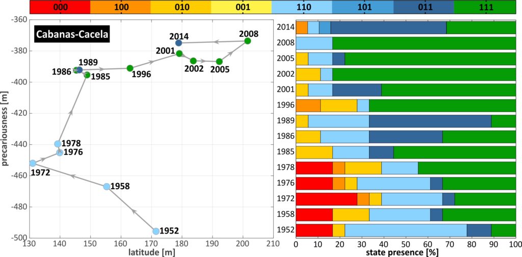
In general, the methodology effectively represents extensive and/or persistent changes in the barrier. Still, important shifts in sectors, like the shift from 111 to 000 in 1958-72 for the central part of C-C are masked when accounting for the entire barrier. It follows that spatial averaging has limitations and scaling issues can become key when attempting to identify regime shifts and assess resilience dimensions. At the same time, spatiotemporal scales of analysis and the meaning of specified resilience (of what to what) are inseparably linked. Spatial averaging, on one hand, can assist in obtaining a broad view of the resilience evolution, which is both necessary and sought after for long temporal and large spatial scales of analysis, and, on the other, it can mask alongshore barrier heterogeneity. Localised perturbations (i.e. blowouts, breaches, overwashes) may or may not dominate a barrier sector, depending on their spatial extension. Therefore, important thresholds and shifts can, potentially, be overlooked when analysing barrier sectors, which emphasises the significance of both spatial averaging and the siting (position, extent, boundaries) of the sectors themselves.
It follows that the representativeness of the results over sectors (threshold, dominant changes and states) can become critical. At the same time, when the objective is the resilience of entire barriers or barrier stretches, some form of spatial unification is unavoidable. Essentially, it comes to a balance of gains and losses between retaining what is important and highlighting the bigger picture, while maximising both would be practically impossible. To increase the broadness of the analysis and results, spatial detail needs to be sacrificed (alongshore averaging) and, in doing so, localised information (e.g. below-threshold values) can be lost. A gradual increase of spacing is proposed to minimise these impacts, passing from individual transects to sectors and when necessary/feasible, to the level of the entire barrier, in a sequence similar to the steps presented here for C-C.
Depending on the objective of the analysis, however, what is considered important can significantly vary. For instance, destructive events that form part of the natural barrier evolution, in principle, should not be considered as loss of resilience, even though they could be associated to a flip to BDM state 000. An example of such events would be barrier losses due to inlet-related processes, like a barrier stretch caught within the path of a naturally migrating inlet, or a breach after infilling and loss of hydraulic efficiency of the old inlet. However, if the focus of the resilience assessment were other than the resilience of the natural system and the barrier itself, such as man-made structures on the barrier (e.g. housing, infrastructure) or the lagoon (e.g. shellfish farms), the interpretation could be significantly different. In other words, depending on the answer to the question ‘resilience of what?’ the same results can have different meaning. In our analysis, C-C presented an ideal example of a resilient barrier at a multi-decadal scale, one that has been capable of reorganising while undergoing change, in response to the enforced conditions of reduced longshore drift. Parts of the barrier, indeed, were destroyed in the process, with temporary loss of resilience. Still, this shift in barrier state was a necessary step (the ‘creative destruction’ phase of Gunderson and Holling (2002)) for the system to reorganise and regain its functions, structure and feedbacks at a position further inland, where the system stabilised, grew and increased in complexity (marsh growth). The collapse of organisation, release of the accumulated resources (sand) and restructuring of the barrier at a shallower position were the natural response of the system that enabled it to reach a new, post-perturbation, morphodynamic equilibrium. Under similar conditions, resilience should be related to if the system was able to reach a new stable state and not if it was destroyed in the process. Therefore, it should be assessed over appropriate temporal scales, similar to the natural regeneration times for each environment lost.
It is important to underline that the C-C barriers were allowed to evolve and rebound naturally, with limited human interference during their reorganisation (Kombiadou et al., 2019b), allowing to examine the natural resilience pathway of the barrier subsystem. In heavily modified barriers, however, that would be difficult or impossible to assess. In fact, even soft shore protection measures can often oppose the natural response of the system, which, after reaching the bifurcation point, would be to pass from the conservation phase to the creative destruction, so that it can reorganise to cope with the changed prevailing conditions. Such actions, characterised as ‘the anthropic force’ by Stutz and Pilkey (2005), intent to force the system to remain at the conservation phase, opposing the natural dynamics that drive it, even though the system has already become too rigid in its control (overly sensitive to external conditions). Practices stabilising or homogenising key elements, in an attempt to control variability in system processes, actually shrink ecological resilience (Gunderson, 2010). Pea Island in Outer Banks (North Carolina, USA) is an example of such practices (jetties and revetments, kilometres of sand bags, constructed dune ridges, and extensive beach nourishments), where the attempts to ‘hold the line’ have proven insufficient and could lead to collapse of extensive segments of the island (Riggs et al., 2009). Such contrasts in dealing with similar conditions highlight how ambiguously and subjectively resilience (and in extension sustainability) can be and has been used, when confused with an anthropocentric, rigid, view of ‘business as usual’. In this case, would a collapse of the island be characterised as loss of resilience, or are the management practices, themselves, opposing barrier resilience? Resilience of complex adaptive systems is not simply about resistance to change and conservation of existing structures (Folke, 2006). To the contrary, evolution and adaption are the core of resilient response and the potential for coastal resilience can only be realised if solutions are attuned to inherent, previously demonstrated, resilience characteristics (Long et al., 2006). There is a need for a paradigm shift in our understanding of resilient natural systems, especially in a future of rapidly changing conditions. Even if we continue to view barrier islands as a first line of storm defence, it is clear that barrier islands do not -and cannot be forced to- behave like coastal works and their resilience needs to be understood and assessed far from rigid principles and predefined barrier dimensions.
This work contributes to the clear translation of resilience concepts into detectable and measurable geomorphic/physical units, adaptable to any geomorphic system. The approach allows assessing resilience through reorganisation and adaptation, far from pre-specified dimension criteria (i.e. pre-disturbance barrier dimensions), in a manner suitable for natural systems, hopefully, providing a step forward towards effective interdisciplinary research and cooperation in the area of sustainability and resilience of natural systems.
Related research project: EVREST: Evolution and Resilience of Barrier Island Systems
Related papers:
- Kombiadou, K., Matias, A., Costas, S., Rita Carrasco, A., Plomaritis, T. A., & Ferreira, Ó. (2020). Barrier island resilience assessment: Applying the ecological principles to geomorphological data. CATENA, 194, 104755. doi: org/10.1016/j.catena.2020.104755. link
- Kombiadou, K., Costas, S., Carrasco, A.R., Plomaritis, T.A., Ferreira, Ó., Matias, A., 2019. Bridging the gap between resilience and geomorphology of complex coastal systems. Earth-Science Reviews, 198, 102934, DOI: 10.1016/j.earscirev.2019.102934. link
EVREST team membes that participated in the work
Coastal morphodynamics modelling
Beach erosion and recovery
The ability of the XBeach model to simulate not only storm-induced erosion, but also the post-storm recovery was tested over a reflective beach (Faro Beach, in S. Portugal) during and after the incidence of Emma storm that impacted the area in early 2018 and caused extensive retreat and flattening of the beach profile. Three profiles (PW, PC and PE) along Faro Beach were monitored during this event, with measured profiles before (26 Feb) and right after the storm peak (2 Mar) as well as 6, 35 and 49 days later (8 March and 6 and 20 April). Recovery in all three profiles showed rapid steepening of the beachface and significant recovery of eroded volumes (68–92%) within 45 days after the storm, while berm heights reached 4.5–5 m. These morphodynamic changes were simulated running XBeach and assuming distinct calibration parameter values for storm and non-storm conditions.
Hydrodynamics were simulated using the surfbeat (instationary) mode of XBeach that resolves short wave variations on the wave group scale and the associated long waves, while wave breaking was modelled using the time-varying dissipation rate mode. A morphodynamic acceleration factor (morfac) of 5 was used in the simulations, while it is noted that the sensitivity of the simulated morphologic changes compared with simulations with no morphologic acceleration was very low. Regarding boundary conditions, an absorbing-generating boundary was considered at the offshore and onshore boundaries, while input wave and SL conditions at the offshore boundary were introduced as Jonswap wave-spectrum and elevation time-series, respectively. The grid step used varied between 0.5 m and 10 m for parts of the profile over the depth of 1 m and below the depth of 20 m, respectively, and non-linearly reducing steps with depth for the intermediate zone. The mean grain size was set to 0.5 mm (D50 = 0.5 mm and D90 = 0.8 mm), as characteristic for the beachface sand distribution. Among the different calibration parameters tested, two were the most critical: (a) bermslope: coefficient that nudges the slope of the profile near the waterline towards its value, leading to a strong local onshore transport when the actual slope is less than the value of the coefficient; and (b) facua: factor expressing the combined influence of wave skewness and asymmetry to onshore sediment transport.
To improve the runup (incident swash) underestimation by the surfbeat mode of XBeach, critical for the simulated post-storm recovery in steep-sloped beaches like Faro Beach, an artificial boost in sea level (SL) was applied in order to force the runup higher into the profile. This SL boost was assessed by a series of simplified experiments of wave incidence (Hs: 1 to 6m and Tp: 6 to 16 s) were conducted for an idealized bi-linear beach profile, assuming different slopes above and below the depth of 2 m (beachface slopes from 0.056 to 0.13; stable slope of 0.0055 for the submerged profile) and were compared to the analytic expression of Stockdon. In cases of where simulated R2% runup height was lower than the analytic value, a boost in SL was applied, equal to the R2% runup height underestimation (difference between the analytic R2% value and the simulated runup; positive quantity). The correction assisted in improving the XBeach surfbeat simulated runup height, both against the analytic expression, as well as the simulations using the nonhydrostatic version of XBeach. This correction was applied in the model, running each sequential step of XBeach twice for the same forcing conditions: (a) the first time assuming only hydrodynamics, to calculate the runup on the profile morphology (assimilating the morphodynamic changes of the previous step) and; (b) the second time simulating morphodynamics and using the R2% value simulated in step (a) to calculate the SL boost needed to adjust the runup height (if not SL boost was set to 0).
Peak erosion (2 March) was reproduced accurately in all three profiles (shown in the Fig. below for profile PE) with model error mainly related with a slightly lower simulated beachface slope and in PE an overestimation of erosion at the foot of the dune (not present in PW and PC due to riprap protection). Early post-storm recovery (8 March; panel b in Fig.) is near-perfect agreement between simulation and observation, while model performance is also good at the end of the study period (20 April; panel c in Fig.), with a slight overestimation of berm height (3.8 m versus 3.6 m) and underestimation of berm slope (0.116 versus 0.127).
The approximation of runup height range and temporal variability compares well with the theoretical values (panel d in Fig.), following the temporal variability and largely the range of values in all profiles. Significant peaks in the recovery period, some related to longer waves, that were under-represented prior to the runup adjustment applied, are now captured in the simulation, decisively improving the upper range of the active profiles simulated. Simulated morphological changes with time are also given in the plot (in d, shown as profiles and bed level changes per day; top and bottom panels, respectively). The influence of the shift from the erosive calibration variable set to the accretive after the end of the storm can be easily noted, with the gradual berm formation and vertical expansion and seaward progradation. Several jumps in berm elevation can be identified, such as 16 and 30 March and 8 April, that are related to high runup levels in the preceding periods.
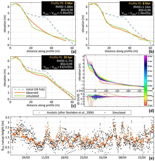
In terms of calibration parameters, the inclusion of bermslope transport term was fundamental to the recovery of the steep slopes of Faro Beach, while balancing wave skewness and asymmetry through the facua term induced the necessary onshore sediment fluxes to balance storm erosion as well as to feed sand recovery. Distinct calibration values were necessary between profiles, even though their alongshore distances are very low. This was mainly due to the different characteristics of the profiles in terms of backshore morphology and constraints, however profile-specific calibration for individual profiles has been proven necessary to improve XBeach performance in other works.
Aeolian morphodynamics
Coastal dunes are sensitive ecosystems whose survival depends on their adaption to changing conditions. Thus, it is important to understand how dune characteristics (i.e., shape, vegetation type, and cover) and prevailing conditions (i.e., wind speed and direction, beach width) determine where and when sand is deposited onto the dune, promoting growth. This is the result of a complex balance between winds that bring sand to the dune from the adjacent beach (main sand provider), the dune topography (decelerating winds near the dune toe and accelerating them along the slope, up to the dune crest) and dune plants (slowing winds down in their vicinity and trapping wind-blown sand). The main controls on these complex interactions have been incorporated into the Duna model for aeolian sand transport. After tuning parameters and verifying that simulated results are accurate, Duna is used to assess the impacts of dune shape (height and slope), beach width, vegetation coverage and wind angles to wind flow and topographic changes on the dune.
The main patterns in aeolian sand accumulation (dV, plotted on y-axes) with dune morphological parameters, wind incidence and potential limiting conditions, identified from the results of the numerical experiments, are summarized in the figure below. The top panel shows the influence of fetch length on sand accumulation on the beach (windward of the dune toe) and on the dune (leeward of the dune toe) and its variability with dune height, stoss slope (plotted on x-axes) and wind incidence (shown as lines in plots). The bottom panel outlines the influence of vegetation density on the volume changes within the dune parts, for variable dune heights and wind incidence. Essentially, the variability of volume gains within the dune of the top panel (dashed rectangles in Fig.) is split here into the zones of stoss slope and dune crest and lee, for sparse and densely vegetated dunes. These patterns are explained and discussed in the following paragraphs.
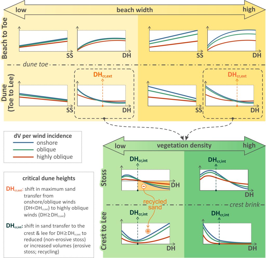
Overall, the sand transport experiments indicate the presence of a logarithmic relation between accumulation and dune height and a linear relation with stoss slope, increasing at the dune toe and decreasing at the dune stoss and crest-lee. Differences in volume changes between onshore and oblique winds were low (reduction of ∼14%) in all experiments, in agreement with other observations over the stoss for different beach conditions. Sand transfer at the toe under NL conditions and highly oblique winds (∼60°) is reduced by around 50%, compared to onshore wind incidence. The latter is in accordance with the cosine effect, showing successful reproduction of the effect by the model, indirectly parameterized by the grid rotation approach. Under FL conditions, the cosine and fetch effects can both affect the accumulation at the toe. There is a tendency for overlapping accumulation volumes at the toe between the different wind bins for low beach widths (Fig.). Under such conditions, fetch limitation dominates the onshore winds and cosine limitation dominates the highly oblique winds. This is in line with previous research, supporting that even though sand transport may be reduced by the cosine effect for highly oblique winds, the actual transport in narrow beaches may be greater than for onshore winds. As beach widths increase, there is increasing separation of accumulation at the toe between wind bins, until NL transport is reached for onshore winds, with reduced accumulation by around 50% (cosine effect) for highly oblique winds (Fig.).
Regarding the accumulation at the dune (landwards from the dune toe), the results show a relation between the dune morphological characteristics and the wind incidence angles. The difference induced to the sand transfer to the dune by an increase in wind obliquity is smaller when the dune is higher and/or steeper. For low dunes, maximum sand transfer to the dune takes place under shore-normal winds, while beyond a critical dune height, that depends on the considered wind (speeds between 5.40 and 22.72 m/s and average of 12.92 ± 2.34 m/s) and beach conditions (∼14–18 m for NL; beach width of 200 m), the balance flips to highly oblique winds. It follows that, above a critical dune height (DHcr,ext in Fig.), highly oblique winds appear to transfer more sand to the dune than onshore winds. Beach width is also relevant to this pattern, with a tendency to lower the critical dune height value (DHcr,ext) as the beach width decreases (i.e., from NL to FL conditions). Therefore, the balance in sand transfer to the dune between wind incidence angles is highly influenced by both the dune height and the beach width: (a) the higher the dune and/or (b) the narrower the beach, the more likely that the highest sand transfer takes place under high incidence angles. The experiments show the presence of a second critical dune height (DHcr,int in Fig.), beyond which the sand transferred to the crest and lee either reduces to near-zero due to high retention over the (non-erosive) stoss, or it is mixed with remobilized sand from the (erosive) stoss. The latter case maintains a significant sand transfer to the crest and lee from the beach, even though volumes also reduce with height and steepness. Lower dunes (<DHcr,int) continue to grow, irrespective of the considered density. Thus, the above point to two different types of evolutionary patterns for high dunes: (a) in cases of densely vegetated (enough to maintain the position of the stoss) dunes, the vertical growth practically ceases and the dune progrades seawards; (b) in cases of sparser vegetation the dune retreats landwards, with high sand transfer to the lee.
The full paper can be accessed in https://doi.org/10.1029/2023JF007080 and the related dataset is available in https://doi.org/10.5281/zenodo.8120830
Related research project: ENLACE: Exploring New approaches to simuLAte long-term Coastal Evolution
ENLACE team members that participated in the work
Related papers:
- Kombiadou, K., Costas, S., & Roelvink, D. (2023). Exploring controls on coastal dune growth through a simplified model. Journal of Geophysical Research: Earth Surface, 128. https://doi.org/10.1029/2023JF007080
- Kombiadou, K., Costas, S., Roelvink, D., (2021). Simulating Destructive and Constructive Morphodynamic Processes in Steep Beaches. Journal of Marine Science and Engineering, 9(1):86. link
- Costas, S., Kombiadou, K., & Roelvink, D., (2020). Exploring the role of vegetation and sediment supply to coastal dune states using integrated process-based modelling, EGU General Assembly, Online, 4-8 May 2020, link
- Kombiadou, K., Costas, S., Roelvink, D., & McCall, R., (2020). Post-storm recuperation as a stepping-stone towards long-term integrated modelling in steep beaches, EGU General Assembly, Online, 4-8 May 2020, link
- Costas, S., Kombiadou, K., & Roelvink, D., (2019). How do multiple beach and dune beach ridges emerge and evolve in prograding coasts?, Proceedings of the 9th International Conference on Coastal Sediments 2019, Tampa/St. Petersburg, Florida, USA, 27 – 31 May 2019, pp. 2282-2295, link
- Costas, S., Kombiadou, K., & Roelvink, D., (2019). On the genesis of new ridges at prograding coasts, X Jornadas de Geomorfología Litoral, 4-6 September 2019, Castelldefels, Spain, pp. 29-32 [full paper]

